Features
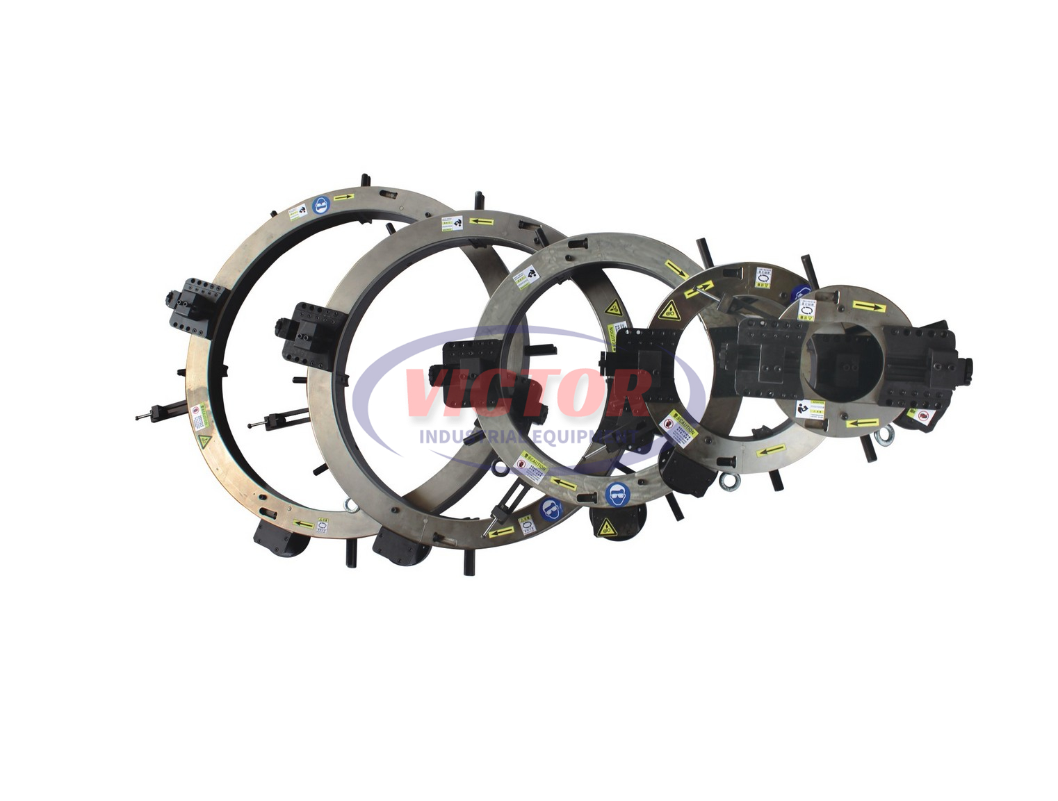
1. This beveling machine has many models, each one can work on pipes with any different diameter in its applicable range just by changing the different swelling ribs.
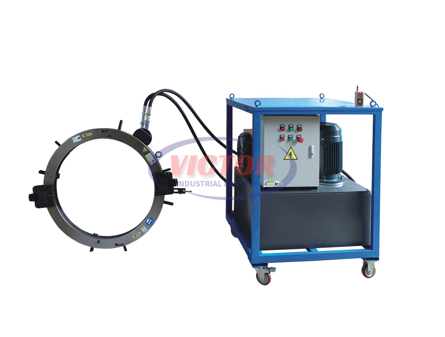
2. Compact, lightweight structure, designed to bevel in the narrow space and headroom in any orientation, No need to rely on other ancillary facilities.
3. Easy installation and stable operation can allow the operator to finish the work easily.
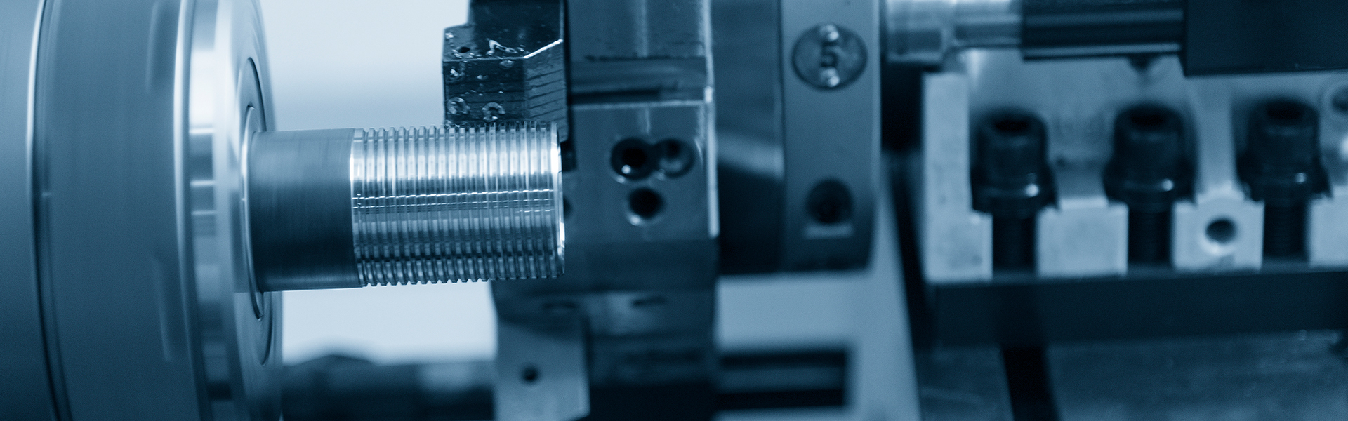
4. As it adopts mechanical cutting beveling method, it can maintain well mechanical properties of the original material so as to avoid using gas cutting groove to burn the pipe material, which seriously affects the welding strength of the pipe.
5. Automatic cutter feeding beveling machine can realize many beveling shapes, such as flat, V shape, X shape, U shape and so on, which can meet the technological requirements for butt welding.
Main Structure and Function
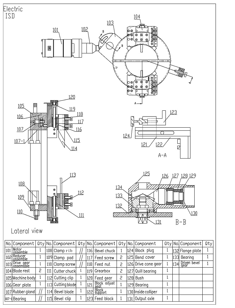
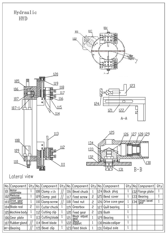
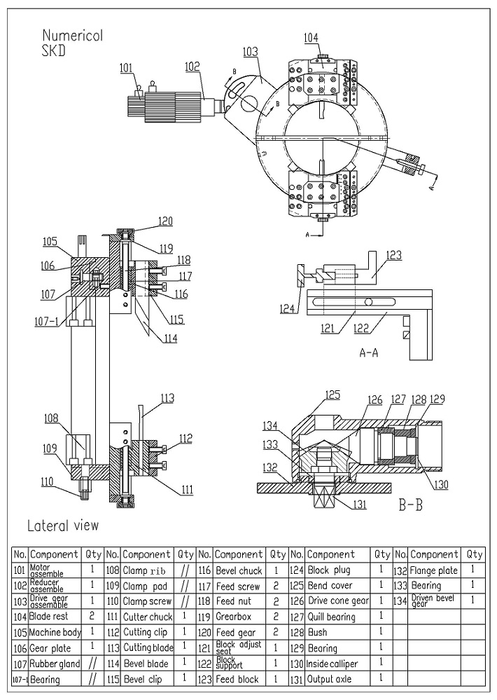
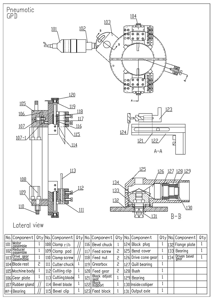
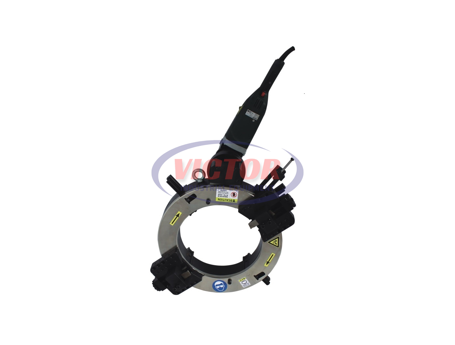
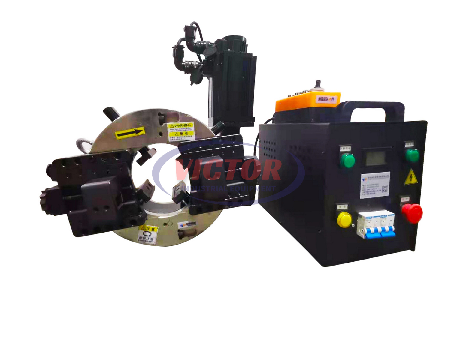
Pipe cutting and beveling machine consists of following 6 parts: motor (includes speed reducer), deceleration system compounded from three planetary gear reducers, clamping device, feeding device, blade and swelling ribs.
Through the motor’s high-speed rotating, multilevel and various forms gear speed change drive system and rotating cutter head around the mandrel, finally the machine outputs the needed rotating speed of the cutter head and cutting force for beveling work.
By manually rotating the swelling column, the radial clamping and contraction of the expansion block mounted on the column can be achieved, and the clamping and positioning of the beveling machine on the pipe can be realized, or the beveling machine can be loosened
The feeding device including outgoing feed and radial feed, consists of two parts, cutting and beveling devices.
Automatic feed device can deliver a even feed schedule by rotating the ratchet wheel on the end of the holder.
Model and Technical Parameters
Model | Pipe O.D(mm) | Wall Thickness(mm) | Motor power/Voltage(KW/V) | No-load speed of cutter head (rpm) | Weight/KG |
N.W | G.W |
VPD-80 | Φ16-80 | 1 -3″ | 3~25 | 1.1~2.5 220V | 20 | 28 | 41 |
VPD-168 | Φ60-168 | 2-6″ | 3~25 | 16 | 40 | 60 |
VPD-219 | Φ80-219 | 3-8″ | 3~25 | 15 | 60 | 85 |
VPD-273 | Φ130-273 | 5-10″ | 3~25 | 14 | 70 | 95 |
VPD-325 | Φ180-325 | 6-12″ | 3~25 | 13 | 80 | 115 |
VPD-377 | Φ219-377 | 8-14″ | 3~25 | 12 | 85 | 120 |
VPD-406 | Φ265-406 | 10-16″ | 3~25 | 11 | 90 | 130 |
VPD-457 | Φ305-457 | 12-18″ | 3~25 | 10 | 95 | 140 |
VPD-508 | Φ355-508 | 14-20″ | 3~25 | 9 | 115 | 163 |
VPD-560 | Φ406-560 | 16-22″ | 3~25 | 9 | 125 | 173 |
VPD-610 | Φ457-610 | 18-24″ | 3~25 | 8 | 135 | 180 |
VPD-660 | Φ508-660 | 20-26″ | 3~25 | 8 | 145 | 190 |
VPD-715 | Φ560-715 | 22-28″ | 3~25 | 8 | 155 | 200 |
VPD-762 | Φ610-762 | 24-30″ | 3~25 | 7 | 170 | 220 |
VPD-813 | Φ660-813 | 26-32″ | 3~25 | 7 | 190 | 240 |
VPD-914 | Φ762-914 | 30-36″ | 3~25 | 6 | 250 | 300 |
VPD-1066 | Φ914-1066 | 36-42″ | 3~25 | 5 | 280 | 340 |
VPD-1219 | Φ1066-1219 | 42-48″ | 3~25 | 5 | 320 | 380 |
Model | Pipe O.D(mm) | Wall Thickness(mm) | Air pressure(Mpa) | No-load speed of cutter head (rpm) | Weight/KG |
N.W | G.W |
VPP-80 | Φ16-80 | 1 -3″ | 3~25 | ≥0.6 | 20 | 28 | 41 |
VPP-168 | Φ60-168 | 2-6″ | 3~25 | 16 | 40 | 60 |
VPP-219 | Φ80-219 | 3-8″ | 3~25 | 15 | 60 | 85 |
VPP-273 | Φ130-273 | 5-10″ | 3~25 | 14 | 70 | 95 |
VPP-325 | Φ180-325 | 6-12″ | 3~25 | 13 | 80 | 115 |
VPP-377 | Φ219-377 | 8-14″ | 3~25 | 12 | 85 | 120 |
VPP-406 | Φ265-406 | 10-16″ | 3~25 | 11 | 90 | 130 |
VPP-457 | Φ305-457 | 12-18″ | 3~25 | 10 | 95 | 140 |
VPP-508 | Φ355-508 | 14-20″ | 3~25 | 9 | 115 | 163 |
VPP-560 | Φ406-560 | 16-22″ | 3~25 | 9 | 125 | 173 |
VPP-610 | Φ457-610 | 18-24″ | 3~25 | 8 | 135 | 180 |
VPP-660 | Φ508-660 | 20-26″ | 3~25 | 8 | 145 | 190 |
VPP-715 | Φ560-715 | 22-28″ | 3~25 | 8 | 155 | 200 |
VPP-762 | Φ610-762 | 24-30″ | 3~25 | 7 | 170 | 220 |
VPP-813 | Φ660-813 | 26-32″ | 3~25 | 7 | 190 | 240 |
VPP-914 | Φ762-914 | 30-36″ | 3~25 | 6 | 250 | 300 |
VPP-1066 | Φ914-1066 | 36-42″ | 3~25 | 5 | 280 | 340 |
VPP-1219 | Φ1066-1219 | 42-48″ | 3~25 | 5 | 320 | 380 |
Model | Pipe O.D(mm) | Wall Thickness(mm) | Motor power/Voltage(KW/V) | No-load speed of cutter head (rpm) | Weight/KG |
N.W | G.W |
VPE-80 | Φ16-80 | 1-3″ | 3~25 | 2.3/220 | 0~20 | 48 | 71 |
VPE-168 | Φ60-168 | 2-6″ | 3~25 | 0~16 | 60 | 90 |
VPE-219 | Φ80-219 | 3-8″ | 3~25 | 0~15 | 80 | 115 |
VPE-273 | Φ130-273 | 5-10″ | 3~25 | 0~14 | 90 | 125 |
VPE-325 | Φ180-325 | 6-12″ | 3~25 | 0~13 | 100 | 145 |
VPE-377 | Φ219-377 | 8-14″ | 3~25 | 0~12 | 105 | 150 |
VPE-406 | Φ265-406 | 10-16″ | 3~25 | 0~11 | 110 | 160 |
VPE-457 | Φ305-457 | 12-18″ | 3~25 | 0~10 | 115 | 170 |
VPE-508 | Φ355-508 | 14-20″ | 3~25 | 0~9 | 135 | 193 |
VPE-560 | Φ406-560 | 16-22″ | 3~25 | 0~9 | 145 | 203 |
VPE-610 | Φ457-610 | 18-24″ | 3~25 | 0~8 | 155 | 210 |
VPE-660 | Φ508-660 | 20-26″ | 3~25 | 0~8 | 165 | 220 |
VPE-715 | Φ560-715 | 22-28″ | 3~25 | 0~8 | 175 | 230 |
VPE-762 | Φ610-762 | 24-30″ | 3~25 | 0~7 | 190 | 250 |
VPE-813 | Φ660-813 | 26-32″ | 3~25 | 0~7 | 210 | 270 |
VPE-914 | Φ762-914 | 30-36″ | 3~25 | 0~6 | 270 | 330 |
VPE-1066 | Φ914-1066 | 36-42″ | 3~25 | 0~5 | 300 | 370 |
VPE-1219 | Φ1066-1219 | 42-48″ | 3~25 | 0~5 | 340 | 410 |
Model | Pipe O.D(mm) | Wall Thickness(mm) | Motor power/Voltage(KW/V) | No-load speed of cutter head (rpm) | Weight/KG |
N.W | G.W |
VPH-80 | Φ25-80 | 1 -3″ | 3~25 | 7.5/380 | 0~20 | 228 | 291 |
VPH-168 | Φ60-168 | 2-6″ | 3~25 | 0~16 | 240 | 310 |
VPH-219 | Φ80-219 | 3-8″ | 3~25 | 0~15 | 260 | 335 |
VPH-273 | Φ130-273 | 5-10″ | 3~25 | 0~14 | 270 | 345 |
VPH-325 | Φ180-325 | 6-12″ | 3~25 | 0~13 | 280 | 365 |
VPH-377 | Φ219-377 | 8-14″ | 3~25 | 0~12 | 285 | 370 |
VPH-406 | Φ265-406 | 10-16″ | 3~25 | 0~11 | 290 | 380 |
VPH-457 | Φ305-457 | 12-18″ | 3~25 | 0~10 | 295 | 390 |
VPH-508 | Φ355-508 | 14-20″ | 3~25 | 0~9 | 315 | 413 |
VPH-560 | Φ406-560 | 16-22″ | 3~25 | 0~9 | 325 | 423 |
VPH-610 | Φ457-610 | 18-24″ | 3~25 | 0~8 | 335 | 430 |
VPH-660 | Φ508-660 | 20-26″ | 3~25 | 0~8 | 345 | 440 |
VPH-715 | Φ560-715 | 22-28″ | 3~25 | 0~8 | 355 | 450 |
VPH-762 | Φ610-762 | 24-30″ | 3~25 | 0~7 | 370 | 470 |
VPH-813 | Φ660-813 | 26-32″ | 3~25 | 0~7 | 390 | 490 |
VPH-914 | Φ762-914 | 30-36″ | 3~25 | 0~6 | 450 | 550 |
VPH-1066 | Φ914-1066 | 36-42″ | 3~25 | 0~5 | 480 | 590 |
VPH-1219 | Φ1066-1219 | 42-48″ | 3~25 | 0~5 | 520 | 630 |
Note: 1. The N.W does not contain accessories.
2. The data of wall thickness in the chart above are suitable for carbon steel.
Operation Procedure for Automatic Blade Feed Beveling Machine
No. | Operation | Operation steps and contents | Notice |
1 | Preparation | 1. Clean up the objects around the beveled pipe | To prevent the accident caused by which the cutter head hits the objects around while rotating |
2.Clean up the pipe end. | If the pipe end is gas cut or has weld bead, the pipe head for beveling needs to be grinded to avoid blade damage. |
2 | Installation of swelling ribs | 1.Measure the pipe O.D. | 1. To ensure that the max swelling diameter is 10mm over the pipe O.D. 2. The shrinkage diameter should be at least 5mm less than the pipe O.D. 3. The below flat surface should be quite close to the oblique surface of the swelling rib to assure firm and stable. |
2. Select suitable swelling rib according to the pipe O.D. in the chart. |
3.Test if the clamp and shrink range can meet the requirement. |
3 | Adjust the cutter head | 4.Feed mechanism, adjust the position of the blade holder to the outside of the pipe(backward adjusting) | Enough feed space should be left for installation in one step according to radial length to be groove cut. |
4 | Clamp and position | 1.Mount the machine body on the outer wall of the pipe. and fix it well. | When positioning, please avoid slope by adjusting the vertical degree between swelling rib and pipe outside wall, and center well according to the scale. |
2.Tighten the screw well with a inner hexagon spanner. | Make sure the clamping is reliable to avoid displacement during working. |
5 | Blade installation | Fix the beveling blade with defined angle on the clamp groove. | Let the blade center to aim at the pipe wall thickness center and secure it by the fastening screw on the cutter head. The end surface of blade should be reliably close to the bottom surface of cutter head or blade holder. |
|
|
6 | Power connection | Get the power cable and insert it into power socket. | The power cable direction should be kept far from the machine body to avoid accident caused by twisting during work. |
|
7 | Beveling | 1. Turn on the motor switch to rotate the cutter head. | 1. Please note the blade shouldn’t touch the end face of the pipe during idling the cutter head. 2. Because the outside wall of the pipe has uneven phenomenon, the start of blade feeding must be absolutely slow. 3. Firstly feed the cutting blade, then beveling blade. 4. If bevel the thick pipe, please try to use the coolant to cool beveling blades and this can prolong blade life. |
2. Manually feed slowly to groove the pipe bevel end. |
3. When the beveling cutter rotates one round and can groove cut to the highest point of the outer wall of the pipe, automatical blade feed can be allowed. |
4.When finish beveling, please firstly shut down the motor and then turn the cutter back to safe area. |
8 | Demount | 1.Cut off the power/air pipe | 1. Please avoid the blade damage when it bumps at the pipe during loosening beveling machine. 2. If all the bevel work is finished, please disassemble the beveling blade and carry out maintenance according to the relevant chapters. |
2. Use the hex wrench to loosen clamping screws. |
3. Pull out the bevel machine from the pipe and place it gently at a fixed place. |
Beveling Blade
Beveling blade is an important part for beveling process. Correct selection and use can realize high efficient and quality beveling work:
1). External installed pipe beveling and cutting machine uses beveling blades with different shapes to groove cut, and then different kinds of beveling shape of pipe end such as flat, V shape, X shape and U shape will be obtained.
2). To choose what material of blade is determined by the processing pipe material. Usually, please choose the blade as following.
*If bevel carbon steel pipe (such as Q235,10#,20# pipe), please use high speed steel blade
*If bevel stainless steel pipe, high strength alloy steel pipe and casting iron, please use cobalt high speed steel blade
3). Keep the blades sharp, and resharpen them if they are worn before use.
The beveling machine is delivered from the factory with 4 high speed tool steel blades that can realize beveling on the carbon steel pipe with maximum wall thickness. Please refer to the common beveling diagram for blade shapes and quantity. User can also choose it according to your own need and order other blades when the listed blades below can’t meet your requirements.
Please tell us the processed pipe material and wall thickness when order beveling machine or blades from us, so that we can suggest suitable machine and blades for you.
Our company’s blades are made of good quality material through optimized design, with the characteristic of good blade and long life. Please do use our beveling blades for the best benefits and beveling performance.
Product Structure Diagrams